|
Key Specifications
Product Description UM5202EEDF is surge rated diode arrays designed to protect high speed data interfaces. This series has been specifically designed to protect sensitive components which are connected to data and transmission lines from over-voltage caused by ESD (electrostatic discharge).
The unique design incorporates surge rated, low capacitance steering diodes and a TVS diode in a single package. During transient conditions, the steering diodes direct the transient to either the positive side of the power supply line or to ground. The internal TVS diode prevents over-voltage on the power line, protecting any downstream components.
The low capacitance array configuration allows the user to protect two high-speed data or transmission lines. The low inductance construction minimizes voltage overshoot during high current surges. This device is optimized for ESD protection of portable electronics. They may be used to meet the ESD immunity requirements of IEC 61000-4-2, Level 4 (±15kV air, ±8kV contact discharge).
Features
- Transient Protection for High-Speed Data Lines to IEC 61000-4-2 (ESD) ±15kV (Air), ±8kV (Contact)
- Array of Surge Rated Diodes with Internal TVS Diode
- Protects Two I/O Lines & Power Line
- Low Capacitance (<2pF) for High-Speed Interfaces
- No Insertion Loss to 2.0GHz
- Low Leakage Current and Clamping Voltage
- Low Operating Voltage: 5.0V
- Solid-State Silicon-Avalanche Technology
Applications
- USB 2.0
- USB OTG
- Monitors and Flat Panel Displays
- Digital Visual Interface (DVI)
- High-Definition Multimedia Interface (HDMI)
- SIM Ports
- IEEE 1394 Firewire Ports
Pin Configurations
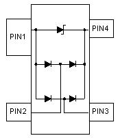 Electrical Characteristics
Note 1: I/O pins are pin 2, 3.
Ordering Information
|
Application Notes
Product Selection Guide
Product Search
Product You Recently Viewed
|